Table of Contents
1 What is optocoupler?
Generally, it is an element used when transmitting signals between isolated circuits, but it also used the place where the ground level is different even if they are electrically connected.
When current flows through the LED on the primary side, the LED emits light and current flows through the phototransistor on the secondary side (switching operation), then the signal is transmitted.
The 1st and 2nd orders are optically coupled, but no electrical signal flows between the 1st and 2nd orders.
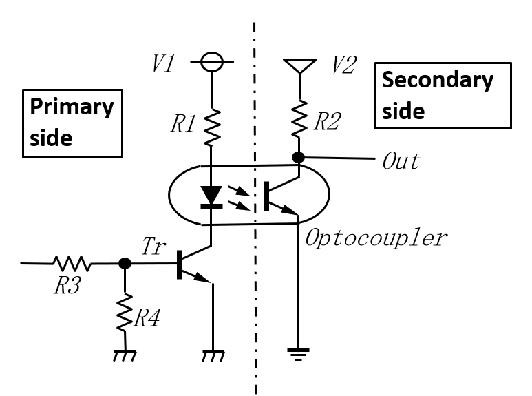
Fig 1 Optocoupler basic circuit
The specific uses are as follows.
1. Switching power supply circuit feedback signal
2. Sending and receiving signals from the microcomputer to the high voltage circuits.
3. Low-speed serial signal when communicating while taking insulation
2 Basics at design rules
Actually, it is troublesome to think about, but the design rules for mass production are as follows.
The current transfer ratio (CTR) when you design is determined by the following formula.
Point
IF x (minimum value of CTR on the datasheet) x (relative CTR by the LED current) x (relative CTR when VCE = 1V) x (lowest relative CTR within the operating temp.) x (relative CTR by aging)> Ic
IF: Primary current flowing through the LED
Ic: Secondary current flowing through the phototransisto
The maximum current passed to the transistor side is about 30mA.
I’d like to explain step-by-step below.
2.1 Current transfer ratio (CTR) changes with IF
The relationship between the current (IF) flowing on the primary side and the current (Ic) flowing on the secondary side.
Figure 2 below is taken from SHARP's PC817 datasheet, and it can be seen that the current 10mA is the peak of CTR, and it means to be able to be flown Ic more than 3 times that of IF.
The datasheet shows the CTR when IF = 5mA, so when 10mA is applied,
reading from the graph, 280/320 = 1.14 times higher CTR.
On the contrary, if you use it at 2mA or 3mA, the CTR will drop.
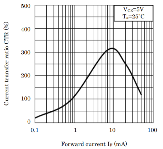
Fig2. CTR vs Forward current IF
If you look closely at this graph, it says VCE = 5V.
What is VCE 5V?
This means, "Although the current transmission is 300%, it does not turn on completely, and the VCE of the phototransistors has the voltage of 5V."
Few people use it this way.
2.2 Current transfer ratio (CTR) that changes with collector-emitter voltage
Let's check the contents related to VCE from another characteristic graph, Fig. 3.
At VCE = 5V, at IF = 10mA, Ic = 13mA (indicated by the orange line), which contradicts what was written earlier as 300%, but the CTR of this photocoupler starts from 50%. There is a wide range up to 600%, so if you used the one with a CTR of 280% in the previous graph.
It would you mean that the characteristic graph this time was measured with 120%.
Every time, I'm worried about how to describe this kind of characteristic graph.
If you use it for switching, I want VCE to be at least 1V or less.
That is, I want to bring the state of the phototransistor to the left side of the blue line added to this graph.
Then, the current transmission ratio is shown in Table 1 below.
Somehow it has fallen below the CTR listed in the datasheet.
I think that it is kinder to the user to write the value when VCE = 1V for CTR, but why every manufacturer uses the same description.
Is it decided by the industry association?
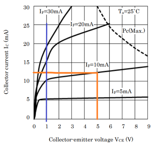
Fig 3 Ic vs VCE
Table 1 VCE vs. CTR
| IF (mA) | VCE=1V | VCE=5V | ||
| Ic | CTR | Ic | CTR | |
| 5 mA | 5 mA | 100% | 6mA | 120% |
| 10 mA | 10 mA | 100% | 13mA | 130% |
| 20 mA | 15 mA | 75% | 24mA | 120% |
| 30 mA | 20 mA | 67% | Could Not read from the datasheet | |
2.3 Current transmission ratio (CTR) that changes depending on the ambient temperature
So far, we have talked about the initial state at room temperature, but in the case of photocouplers, it is necessary to consider the temperature characteristics. See Fig. 4 Relative CTR-ambient temperature characteristics.
The higher the ambient temperature, the lower the CTR.
If you want to use it up to about 50 ℃, you have to think about it will be about down to 80%.
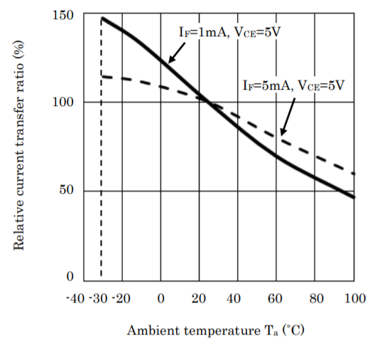
図 4 Relative CTR vs. Ambient Temperature
2.4 CTR changes over time
Precautions for aging deterioration in the case of PC817, it is described as follows.
Aging The infrared light emitting diode used in the photocoupler generally reduces its light emission output when energized. When using for a long time, please design the circuit in consideration of the output decrease (50% / 5 years) of the infrared light emitting diode.
Is it 50%?
There are many doubts about its value. CTR decreases when current is continuously applied to the LED, but some manufacturers disclose the change due to the current value and energization time in a graph.
My feeling is that if the current is about 5mA, the decrease is 20% or less. Detailed materials may come out when you contact the manufacturer.
3 Conclusion
From the above, let's calculate the CTR that should be considered at the time of design. Rewrite the formula mentioned at the beginning.
IF x (minimum value of CTR on the datasheet) x (relative CTR by the LED current) x (relative CTR when VCE = 1V) x (lowest relative CTR within the operating temp.) x (relative CTR by aging)> Ic
Let's apply this to the design of an actual optocoupler.
Let's assume that V2 is 5V, R2 is 500Ω, Ic is 10mA, and the maximum operating temperature is 50℃ in the basic circuit Fig1.
(1) CTR by LED current 320/280 = 1.14 (see Fig. 2)
(2) CTR when VCE = 1V 100/130 = 0.77 (see Table 1)
(3) CTR based on temperature characteristics 0.8 (see Fig. 4)
There is no graph when IF = 10mA, but it is almost like this.
(4)CTR due to aging 0.5
The photocoupler PC817 has four CTR ranks A to D, and the CTR when the IF is 5mA is listed. Each value is as follows.
Rank A 80 - 160
Rank B 130 - 260
Rank C 200 - 400
Rank D 300 - 600
If you use C rank, the minimum value of CTR of C rank is 200, so multiply by the magnification from (1) to (4).
200×1.14×0.77×0.8×0.5=70
How is it?
The original CTR 200 falls down to 70.
This means that if you try to flow 10mA to the secondary side, you must flow 10mA / 0.7 = 14m to the primary side to configure a highly reliable circuit.
Then, the value of the resistor R1 in Fig. 1 is that the voltage V1 is 5V.
5V / 14mA = 357Ω
If you use E6 series resistors, you need to use 330Ω.
Some people use optocouplers at full rank without specifying the rank, but I do not recommend it. If the minimum CTR listed in the datasheet is 50%, it becomes 17.5% in this case.
I always use one of its lowest CTR being 200 or above.